 |
 |
|
|
| Added: |
>
> |
Remove:
Q34
|
| Changed: |
<
< |
| >
> |
|
|
|
| Added: |
>
> |
READ CAREFULLY: The procedure to add IABs is different depending on how they are wired. One IAB wire will always run to the ECU, the other will run to either +12v or gnd. Choose the procedure to match how your car is wired! This is very important!
USDM ODB1 B18C: ( ECU sends ground, IAB wired to +12v )
|
| Changed: |
<
< |
ODB2 & JDM B18C conversions: (signal is reversed)
| >
> |
ODB2 & JDM B18C conversions: ( ECU sends +12v, IAB wired to GND ) |
|
|
| Changed: |
<
< |
IAB conversion...
| >
> |
IAB conversion... (this is for Manual cars only, but an AUTO USDM ECU converted to manual will have all the parts you need present)
Remove:
R135...11F0/1720 autos only
R150...1980/LS only
|
| Changed: |
<
< |
Remove:
R135...11F0/1720 autos only
R150...1980/LS only
| >
> |
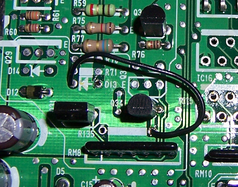
- Jumper wire for OBD1 IAB control:
|
| Added: |
>
> |
|
| Added: |
>
> |
%META:FILEATTACHMENT{name="P28_IAB_OBD1.jpg" attr="" comment="Jumper wire for OBD1 IAB control" date="1121190086" path="P28_IAB_OBD1.jpg" size="266030" user="m2prelude" version="1.1"}% |
|
|
| Added: |
>
> |
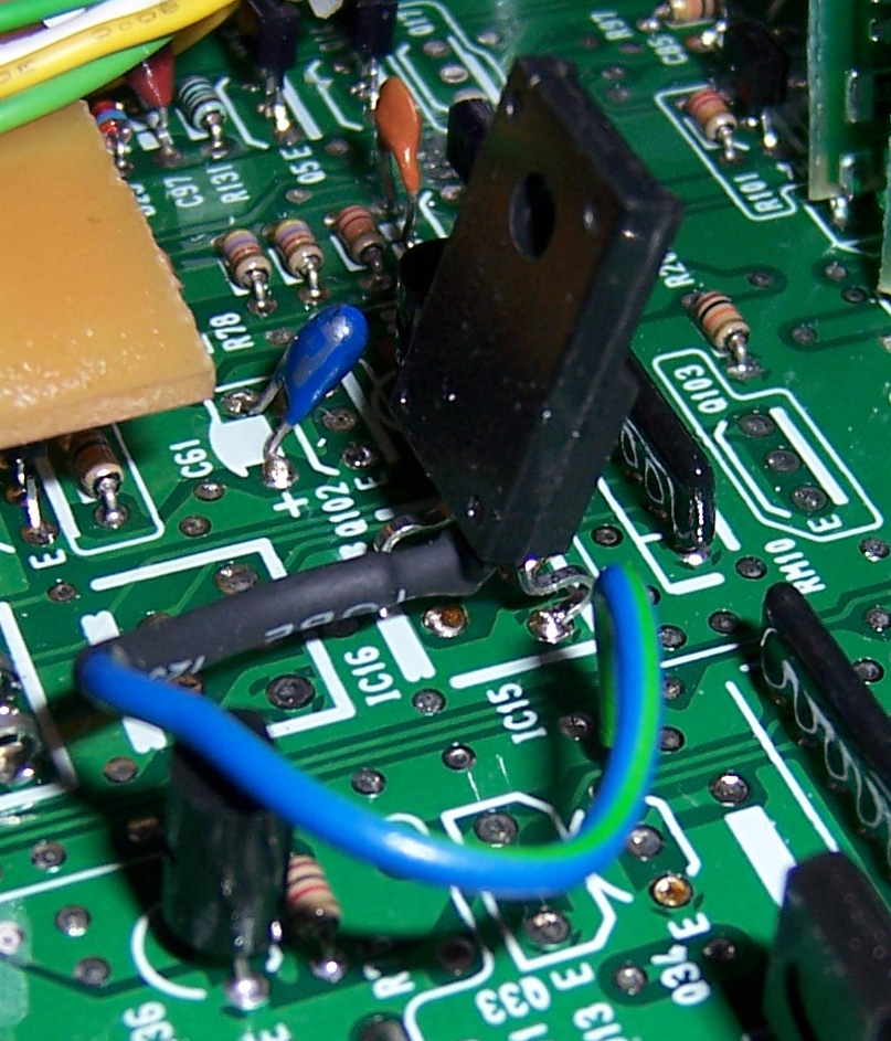
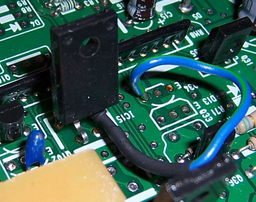
- High side switch for OBD2 IAB control:
- High side switch for OBD2 IAB control:
%META:FILEATTACHMENT{name="P28_IAB_1.jpg" attr="" comment="High side switch for OBD2 IAB control" date="1121176716" path="P28_IAB_1.jpg" size="364224" user="m2prelude" version="1.1"}%
%META:FILEATTACHMENT{name="P28_IAB_2.jpg" attr="" comment="High side switch for OBD2 IAB control" date="1121176803" path="P28_IAB_2.jpg" size="212634" user="m2prelude" version="1.1"}% |
|
|
| Changed: |
<
< |
obd2 conversions: (signal is reversed)
| >
> |
ODB2 & JDM B18C conversions: (signal is reversed)
|
| Changed: |
<
< |
- cut control leg of IC15 short and solder signal carrying wire to it (thread wire through hole)
and solder other 515 X High Side Switch pins in place
| >
> |
- cut control leg of IC15 short and solder signal carrying wire to it (thread wire through hole)and solder other 515 X High Side Switch pins in place
|
| Added: |
>
> |
- add Q17(A143)...already present on USDM auto 11F0/1720 (A5x, L5x, etc). Not present on EDM auto 11F0/1720 (G5x, etc).
|
| Added: |
>
> |
Pin A19 will be your IAB output on the OBD1 harness. |
|
|
| Changed: |
<
< |
- Q34(D1980? or C3225?)... already present on USDM auto 11F0/1720 (A5x, L5x, etc). Not present on EDM auto 11F0/1720 (G5x, etc). may use PCS trans: Q31(D1980?)
| >
> |
- Q34(D1780 or C3225?)... already present on USDM auto 11F0/1720 (A5x, L5x, etc). Not present on EDM auto 11F0/1720 (G5x, etc). may use PCS trans: Q31(D1780)
|
|
|
| Changed: |
<
< |
- Q34(D1980? or C3255?)... already present on USDM auto 11F0/1720 (A5x, L5x, etc). Not present on EDM auto 11F0/1720 (G5x, etc). may use PCS trans: Q31(D1980?)
| >
> |
- Q34(D1980? or C3225?)... already present on USDM auto 11F0/1720 (A5x, L5x, etc). Not present on EDM auto 11F0/1720 (G5x, etc). may use PCS trans: Q31(D1980?)
|
|
|
| Added: |
>
> |
%META:TOPICINFO{author="blundar" date="1078516726" format="1.0" version="1.1"}%
Author: Deluded Date: 07-24-03 23:44
IAB conversion...
Add:
- Q17(A143)...already present on USDM auto 11F0/1720 (A5x, L5x, etc). Not present on EDM auto 11F0/1720 (G5x, etc).
- Q34(D1980? or C3255?)... already present on USDM auto 11F0/1720 (A5x, L5x, etc). Not present on EDM auto 11F0/1720 (G5x, etc). may use PCS trans: Q31(D1980?)
- jumper from right hole of R135(trans side) to D13(arrow side)
Remove:
R135...11F0/1720 autos only
R150...1980/LS only
obd2 conversions: (signal is reversed)
- above procedure not needed...
- cut control leg of IC15 short and solder signal carrying wire to it (thread wire through hole)
and solder other 515 X High Side Switch pins in place
Use P72 code with knock disabled .
Similar install on LS ecus. |
|
Copyright © 2002-present by the contributing authors. All material on this collaboration platform is the property of the
contributing authors, and is covered by the Non-Commercial Share-Alike License unless explicitly stated otherwise. |
|