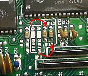
Removing the knock detection is simple: Resolder R118 and R119 into R142, 143. Then, Remove R101 (optional). Finally, remove the knock board itself.
- no_knock.jpg:
Here's what a knockless P14 looks like: CLick Here!
Originaly posted by prelude-driver
here is how it works,
R101 is a current limit to a signal on the KS, you need it with KS but you can leave it in because it does not go anywhere else.
R118/119 are current limiters on the clock & data signals to the KS,
if you remove the KS you must remove them because of the next resistors.
R142/143 are pullup resistors for the clock & data lines,
you dont use them if you have a KS because there are pullups on the KS itself, but if the KS is removed then you must fit these to stop the lines from floating.
they are 10k btw.
| Attachment?: | Modify: | Size: | Date: | Who: | Comment: |
|---|
 no_knock.jpg no_knock.jpg | mod | 31356 | 26 Jan 2006 - 05:00 | synoptic | |
|
Copyright © 2002-present by the contributing authors. All material on this collaboration platform is the property of the
contributing authors, and is covered by the Non-Commercial Share-Alike License unless explicitly stated otherwise. |
|